
Send values to the camera system.
DeviceJockey → XML gateway → Camera
Set fixed values, map a Slider or Rotary, change a value relatively, or request current information.
DeviceJockey
Interfaces
Control camera functions and reflect their current values on a custom DeviceJockey panel.
Grass Valley XML Control
DeviceJockey connects to XML Control on a CCS one or MCP 450. Commands send camera values through the gateway. Events use values returned by the camera system to update Items or perform their actions.
Set fixed values, map a Slider or Rotary, change a value relatively, or request current information.
Move a Slider, update a label, change an Item state, or perform actions when a matching value arrives.
The same connection carries outgoing control, requests, subscriptions, responses, and camera updates.
System architecture
Grass Valley cameras and control panels communicate within the C2IP camera network. A CCS one or MCP 450 provides the XML gateway to the public network. DeviceJockey connects to that gateway, not directly to an individual camera.
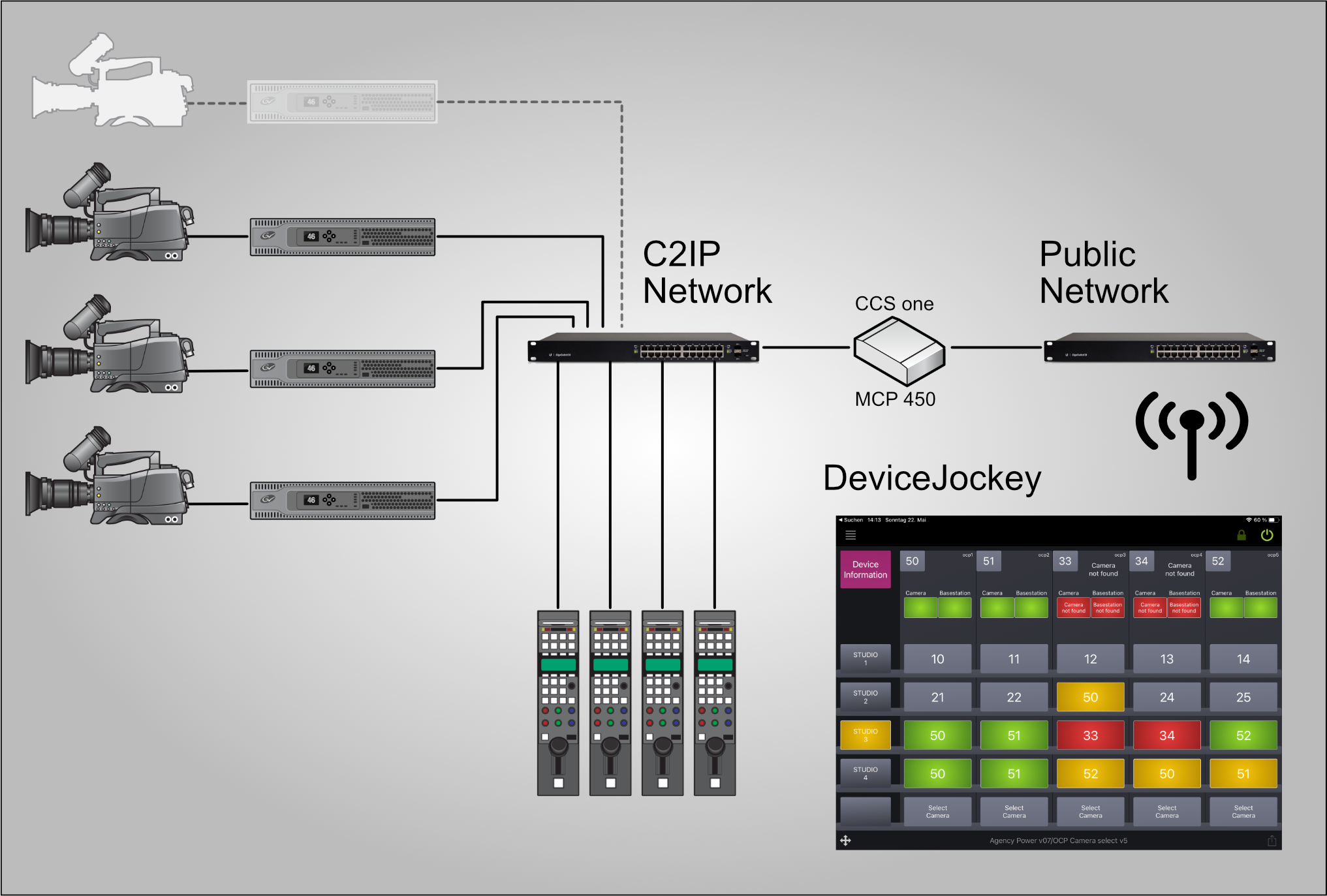
Use the IP address and XML Control port of CCS one or MCP 450 in the DeviceJockey interface settings.
Setup
Open CCS one or MCP 450 and start XML Control.
Add a GV Camera interface to the scene containing your camera-control panel.
Configure host, port, application name, protocol version, and the required response level.
Switch on interface connections and confirm that DeviceJockey appears in the XML Control client list.
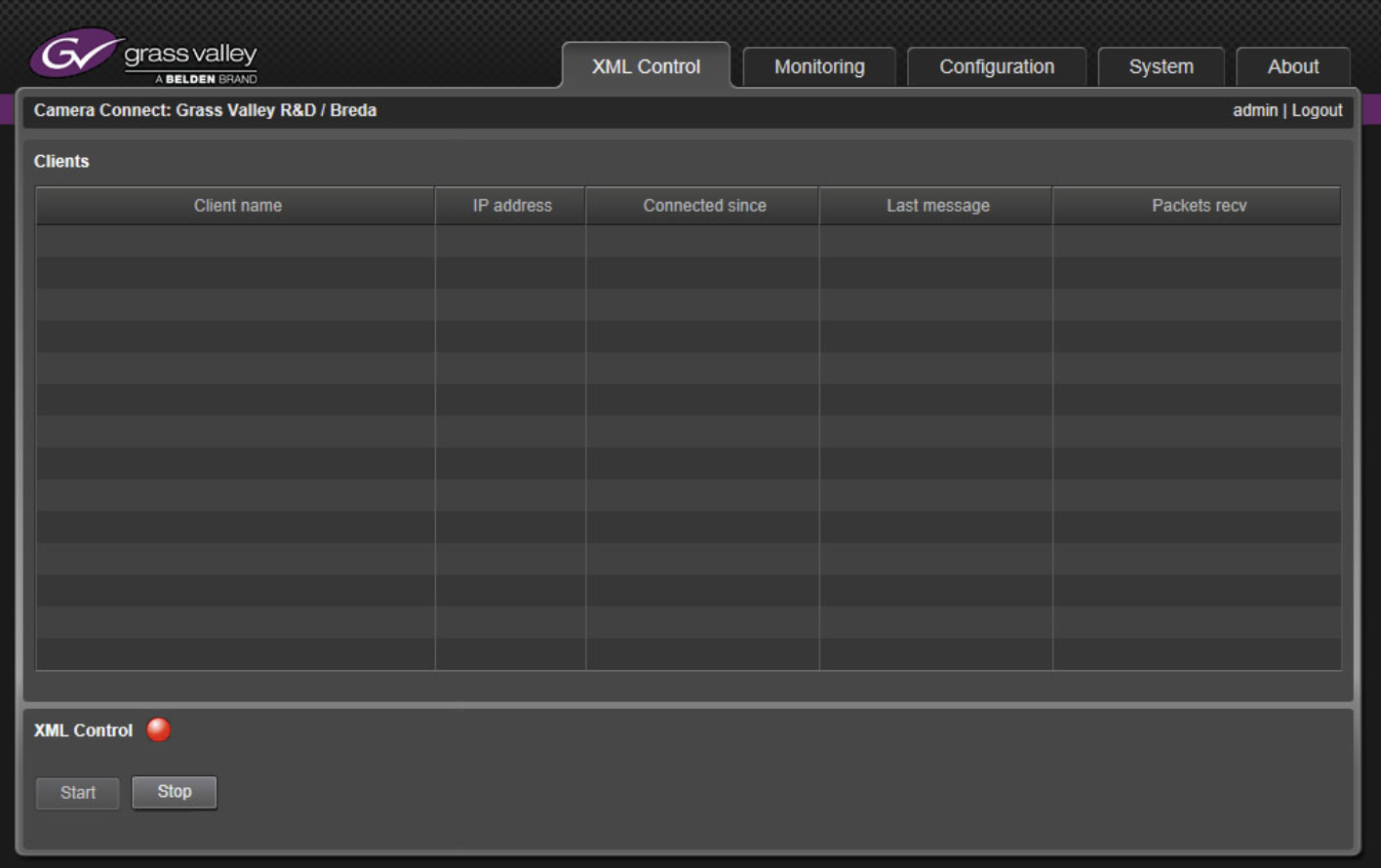
If it returns to its disconnected state, check the address, XML Control, and the network connection before configuring camera lists or functions.
Interface settings
The IP address or host name of CCS one or MCP 450 on the network reachable from the iPhone or iPad.
The port configured for XML Control in the Grass Valley gateway.
The client name with which DeviceJockey identifies itself to the gateway. The default is DeviceJockey.
The XML protocol version expected by the gateway configuration. The default is 2.0.
Select Never, Always, or ErrorOnly according to how the gateway should return command responses. The default is Never.
Commands →
Send a specific value to a selected function of a device.
Send a variable value, for example from a Slider or Toggle, to a function of a device.
Change the current function value by a relative amount instead of setting an absolute value. The amount can also come from the Item title.
Ask the user for a value when the Command runs and send the entered value to the selected device function.
Request the current value of a selected device function. The returned value is received by DeviceJockey as an incoming Grass Valley Event.
Subscribe or unsubscribe to updates for a selected device function.
Subscribe or unsubscribe to updates associated with the selected device.
Open a searchable function list. Enter a Device Name (camera number) or Device ID to show all functions of that device, or leave both empty to show all functions known to DeviceJockey. Use the search field to filter the list.
Open the device-information list populated from the connected Grass Valley system. Enter a Device Name (camera number) or Device ID to limit the displayed device information.
Open the connected-device list, let the user select a device, and store either its camera number or its Device ID in a chosen Swap. The optional status check immediately refreshes Items that use the changed Swap.
← Events
React when the selected device and function report the configured value.
Map the current device value into the range of a Slider, Rotary Item, or another supported property.
Display a returned function value or its matching option as an Item label. Options can be entered manually or loaded automatically from the function information. The result can also be formatted with a Script or saved as the Item's new title.
Enable interaction with a supported Item when the selected device and function report the configured value.
Protect a supported Item from interaction when the selected device and function report the configured value.
React to the CCS grouping state, Group ID, CCS Name, or CCS Location. Depending on the Item action, the Event can update a label, switch an Item, control its light, or perform touch and tap actions.
Enable Subscribe in a GV Value, GV Range, or GV Label Event to request its current value during the panel status check and continue receiving updates. A separate Subscribe Command is not required for that Event.
DeviceJockey
Agency functions
In addition to native Grass Valley function IDs, DeviceJockey provides Agency functions gv001 through gv021. They combine device information and camera-system state into values that can be selected from the function list like other functions. Most are intended for Events. The two switching and naming functions marked below are Commands.
gv001 checks whether a device is available. gv004 returns its associated camera number, gv008 its alias, and gv009 its Device ID. gv011 checks whether a particular camera is available.
gv002, gv003, gv005, gv006, gv007, and gv010 report whether a camera or basestation selected through an OCP/CGP or basestation/XCU is available and return the connected basestation ID, camera ID, or camera alias.
gv013 reports whether an OCP/CGP camera switch is active. gv014 returns its destination camera number. gv015 checks whether a camera is selected, while gv016 combines selected and available state.
gv012 switches an OCP/CGP to a camera number. gv017 changes the alias of the camera system currently selected by an OCP/CGP.
gv018 through gv021 check combined red/yellow, red/green, red/green/yellow, and green/yellow Tally states.
Agency functions can apply to all devices or specifically to a camera, OCP/CGP, or basestation/XCU. Their list entries describe the required Device ID, camera number, available options, and returned values.
Example
This example follows the complete control-and-feedback pattern used throughout DeviceJockey: a Command changes red gain, while an Event makes the same Slider follow changes from an OCP/CGP or another controller.
The Command expresses the requested change. The Event shows the state confirmed by the camera system.
Advanced commands
Send a complete raw XML message to the gateway for functions not covered by a standard command.
Insert a mapped item value into the {$value} placeholder of a raw XML message.
Turn CCS grouping on or off and set its Group ID. DeviceJockey converts the Group ID to uppercase. Use a letter from A to Z. A Swap or the Item title can provide the Group ID dynamically.
Set the CCS Name, CCS Location, or both. Each field can be enabled independently and can use a fixed value, a Swap, or the Item title.
For a supported Label action, choose Group ID, CCS Name, or CCS Location as the displayed CCS value. Other Item actions compare grouping and naming data and react when the configured state matches.
Prefer the standard device and function commands when they cover the required camera control.
Troubleshooting
Confirm that XML Control is running on CCS one or MCP 450.
Compare the DeviceJockey interface settings with the current public-network settings of the gateway.
A connected DeviceJockey client should appear in the XML Control window.
The iPhone or iPad must be able to reach the public-network side of the gateway.
Reconnect before opening device and function lists when the camera system has changed.
Use the exact function identifier and the minimum and maximum provided for that function.
Confirm whether the Command or Event uses the Device Name (camera number) or the Device ID.
Use the response behavior required for the gateway workflow and inspect the interface log for errors.